Wednesday, April 30, 2008
Since I have published “Radiation Hardened Memory in Space” in April 2006, the company has sold quite a few radiation memory testers based on our small SP3000 platform. Users have a lot of success in sorting out usable chips for space flights. Yet, their common feedback is that they want a faster error capture to increase their sorting efficiency. CST listens to its customer: a new advanced radiation tester call Eureka II Radiation Tester was born. This new generation memory tester increases the test speed by a factor of 5X and the error capturing speed by a factor of 100X. These features constitute to a very attractive yet low cost tester that will soon become the standard in the industry. This (Part II) article highlights the new tester features and explains how it can help to enhance the sorting efficiency and productivity. Some of the texts from (Part I) are repeated here to allow a complete picture presentation.
Click this link to read Part-1 published in 2006
http://www.simmtester.com/page/news/showpubnews.asp?title=Radiation+Hardened+Memory+in+Space&num=135
Sources of radiation
Electronic memory performance is highly affected by cosmic rays. While we have the ozone layer to shield us from radiation while we are on earth, the picture changes once our computers are above the earth’s ozone layer. The explosive energy from the sun and stars can generate tremendous waves to wipe out memories in our space vehicles. The sun produces electromagnetic radiation of particles in the form of x-rays and gamma rays. Cosmic rays from other stars produce ionizing radiation primarily in the form of protons, nuclei, electrons and gamma radiation.
What does radiation do to the memory?
There are basically 3 types of radiation disruption effects in space flight. The most serious is DDD, Displacement Damage Dose effect. In this case, the radiation is sufficiently strong to cause permanent damage to the semiconductor memory cells. The next is TID, Total Ionizing Dose effect. They slowly ionize the chip changing balance of energy. It makes some switches harder to turn on and the others harder to turn off. This makes the memory operation highly un-predictable. The 3rd type is SEE, Single Event Effect. SEE happen when the collision of a radiation particle with a chip produces enough energy to cause a “soft error” in the memory system.
Focus in Single Event Effect
Luckily, SEE in memory is recoverable once the radiation level returns to normal. The soft error cells can be re-written and errors might never happen again until the next high dose of radiation comes through.
How to make memory work in space?
There are two ways to make memory work in space. One is to invent better semiconductor process to make the memory cell less susceptible to direct radiation. Researchers found that performance under radiation can be improved by repositioning various component junctions or by using Silicon-On-Saphire (SOS) or Silicon-On-Insulator technologies (SOI). Increasing the separation between circuit elements reduces the likelihood that the energy of a radiation strike in one part of the chip will affect enough of the circuit to be a problem. Additionally, on-chip wires can be made thicker to allow for greater current to flow through should a high-energy particle strike. All these methods require redesign of the memory chips and calls for new process technologies that is not widely used for memory chips. That presents a risk in production cost and in scalability when memory technology changes.
The other way is to use off-the-self memory parts. Engineers found that every memory chip exhibits slightly different characteristic under radiation environment. Even the same batch of chips can react quite differently among each other. Some chip work better in the energy environment while others fail miserably. Therefore, the most economical way is to test-and-select. NASA decided to use Off-the-shelf parts even in the International Space Station. This is obviously for cost reason and to allow upgrade path as memory technology advances during their course.
How is radiation test performed?
Since more tests can yield radiation hardened memory chips, the focus is now turned to “how to test them for radiation hardening?” The answer is quite simple. Even a low cost memory tester can fulfill the task.
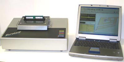
The device under test (DUT) is placed in a chamber under radiation and particle bombardment. The tester head should have a four inch “riser” to elevate the DUT from the tester. This is to allow the beam to focus onto the chip and not to the rest of the tester. To protect the test operator, a 10-foot cable is connected from the tester to the control PC. The operator controls the tester at a safe location outside of the radiation chamber. He can still control and observe test results through the remote PC controller.
(Picture showing Eureka II tester with riser/converter for focus beam.)
Radiation is usually applied to the DUT for a very long period of time to induce SEU, Single Event Upset. Once a cell is upset, it usually stays as an error until the memory content is renew or rewritten. Therefore, the test result has no direct relationship with test time. This factor allows the very low cost memory tester to come into the play. The most important thing is, therefore, the test algorithm.
Experience tells us that the following six steps are needed in radiation memory test:
1. Write_Refresh Test (Special Test Feature)
This is a test specially designed for SEU detection in a radiation environment. This test consists of a “Write Only”, “Refresh Only” and a “Read and Compare” function.
The user first selects the test pattern he wants to write into the chip. For example “00” will allow it to repetitively write 8 consecutive 0’s while “FF” will force it to repetitively write 8 consecutive 1’s into the DRAM cells.
After the “Write” is completed, the tester goes into “Refresh Only” mode and wait for next control instruction. During that time, radiation particle bombardment to the DUT is performed for as long as the operator desire.
After the radiation is completed, the “Read and Compare” function is activated to examine the single event upset by the bombardment. The error locations are identified, and the number of total cell error is accounted. The error report can be saved into a “txt” file for further analysis.
2. Write_Read_Readback Test (Special Test Feature)
This is a test specially designed for SEU detection in a radiation environment. This test consists of a “Write Only”, “Blank Read ” and a “Read and Compare” function.
The user first selects the test pattern he wants to write into the chip. For example “00” will allow it to repetitively write 8 consecutive 0’s while “FF” will force it to repetitively write 8 consecutive 1’s into the DRAM cells.
After the “Write” is completed, the tester goes into “Blank Read” mode and wait for next control instruction. During that time, radiation particle bombardment to the DUT is performed for as long as the operator desire.
After the radiation is completed, the “Read and Compare” function is activated to examine the single event upset by the bombardment. The error locations are identified, and the number of total cell error is accounted. The error report can be saved into a “txt” file for further analysis.
3. Write_Write_Readback Test (Special Test Feature)
This is a test specially designed for SEU detection in a radiation environment. This test consists of a “Write Only”, “Repeating Write Only” and a “Read and Compare” function.
The user first selects the test pattern he wants to write into the chip. For example “00” will allow it to repetitively write 8 consecutive 0’s while “FF” will force it to repetitively write 8 consecutive 1’s into the DRAM cells.
After the “Write” is completed, the tester goes into “Repeated Write Only” mode and wait for next control instruction. During that time, radiation particle bombardment to the DUT is performed for as long as the operator desire.
After the radiation is completed, the “Read and Compare” function is activated to examine the single event upset by the bombardment. The error locations are identified, and the number of total cell error is accounted. The error report can be saved into a “txt” file for further analysis.
4. Read Back Function (Special Test Feature)
The tester also have 3 readback mode specially designed to perform Radiation tests.
The “ReadBack” mode is a simple “Read and Compare” function to examine the single event upset by the bombardment. The error locations are identified, and the number of total cell error is accounted. The error report can be saved into a “txt” file for further analysis.
5. Precharge_MRS_Readback Function (Special Test Feature)
The “P-M_RB” function is similar to the “Read Back” function with the exception that it performs a precharge and mode register reload before it goes into the “Read and Compare” function to examine the single event upset by the bombardment. The error locations are identified, and the number of total cell error is accounted. The error report can be saved into a “txt” file for further analysis.
6. ReWrite_Readback Function (Special Test Feature)
The “RW_Rbk” function is similar to the “Read Back” function with the exception that it performs a single rewrite before it goes into the “Read and Compare” function to examine the single event upset by the bombardment. The error locations are identified, and the number of total cell error is accounted. The error report can be saved into a “txt” file for further analysis.
Eureka II Memory Tester Advances Test Speed 5X
In the last couple of years, integrated circuit technology has evolved to bigger blocks and higher speed. Memory controller can now be constructed out of smaller line geometry of 65nanometer. The number of usable gates in a define area have been greatly expanded. As a result, slow operations can now be speed up many times using pipe-line technology. That is to transform previously software executed function into hardware blocks. They are thus executed like software macros. Software command calls on hardware constructed macros to speed up the overall operation. It is now possible to increase the test speed by a factor of 5X when compared with the conventional test method.
Error Capture for Analysis and Record is Needed
The memory tester has to have capability to map the locations of the radiation sensitive cells. It has to record the address and bit columns of the upset cells. The feature is called “Error Bit Map” or “Error Capture”. Conventionally, error recording is a slow process because the software has to intercept the error location (address and data position) and move it into the computer memory for the record. Each software “move” operation takes micro seconds of execution time. Computer system clock and synchronization comes into play to delay the process.
The new Eureka II test platform has built-in hardware error capture buffer. The buffer is 144bit wide and 2Kbit deep. That means the error information will be recorded into hardware memory right next to the error bit comparator. When an error is detected, the comparator quickly pushes the error signature (address and data bit) into the adjacent static RAM memory buffer in real time. The test is allowed to continue without interruption. When the 2K deep buffer is filled up, the test will then quickly transfer the error data onto the onboard DRAM memory and then reset the 2K buffer for new error data. This process allows the error capture to be 100X faster the conventional error capture method and highly increased the tester efficiency.
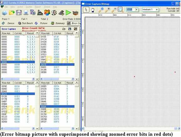
An error capture function is not complete without an easy user interface and display. The Eureka II tester includes a unique graphical error bit map display. The interrupted cell locations are indicated by red dots over a background of good cells. Zooming and numerically indexed grid charts visually presents the exact location of the interrupted memory cells. This bitmap information is also saved into log file for further analysis. The log files are in text format to allow export to other analyzing programs easily.
Based on the SEU rate and their rate of recovery, engineers will be able to determine which chip qualifies to be used in space application.
System application on Radiation hardened memories
Since SEU in memory will definitely occur in space flights, there are computer architectural strategies to keep the systems in operation. One way is to mirror the memory system hoping that the radiation upset on one system is different than the other. By using comparison, the error locations can be verified and an error correction algorithm can be applied to “correct” the upset bits. The computer system can thus operate normally in the abnormal environment.
Since most memory error correction algorithms are based on 1 bit error within an eight bit word, radiation test can be made to discriminate any memory chip that has more than one radiation sensitive cell with the 8 bit word. Since the error bit map is available from the test, the clutters of sensitive cells can be located. Address scrambling method in the system can be applied to “spread out” the errors into different 8 bits words resulting in no more than 1 error per 8-bit word.
Of course, there are also many other system tricks that allow the computer to perform properly with less than perfect memories.
Conclusion
Radiations in space can cause memory failure on in flight computers. Radiation hardening test can select memories that are least susceptible to radiation conditions. Radiation memory testers do not have to be expensive. They can be a simple modified version of a standard low cost memory tester. Smart system architecture would allow selected memories to be used safely in space systems.
Article by : Cecil Ho
By: DocMemory
Copyright © 2023 CST, Inc. All Rights Reserved
|